When you are specifying or designing a system it is generally necessary to keep a collection of documents, such as the P&ID's, Process descriptions and so on. Often these documents can become superseded by a model, but it is always useful to be able to refer back to them, to ensure traceability and to be able to check back. Keeping track of these can be tedious.ControlDraw has long supported simple hyperlinks, provided you had a web or file address on the first line of an object's text. This has been greatly improved recently.
You can now set a Linked Documents Path that is a top level folder that contains all the documents that you want to be able to open from a model.
You can also copy File Names in Explorer and then paste them as hyperlinks.
Friday, 23 July 2010
Thursday, 15 April 2010
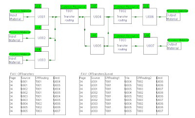
The Transfer Route Queries
You may not know about this although it has been possible for a long time
If you draw a diagram that shows connections between units via common resources there are standard queries that can show a table of the routes, including those that go from unit to unit (single level) , those that go from onne unit to via another unit to the last unit (2 levels) and those that go from a unit to another via two units (3 levels).
The diagram below show a simple example.
For convenience the single level and two level queries are also shown on this diagram using FAV: UserQuery special objects.
Wednesday, 14 April 2010
New - Tag Balloons
The latest version of ControlDraw provides a new way of attaching text to symbols, these are call Tag Balloons and are based on the ISA tag symbols for P&ID's. The picture below shows how to set them and the styles. Click to enlarge.  You can now set the tagname to appear separately from the object in a variety of shapes as shown above. You can then drag the tagname to position it relative to the object.
 You can now set the tagname to appear separately from the object in a variety of shapes as shown above. You can then drag the tagname to position it relative to the object.
Tag balloons are auto sized and split the first letters before the number part and the remainder.
The position of the tag balloon is stored relative to the object so you can use Copy and Paste Object properties to set other tag balloons the same - just click the Appearance button in Paste Object properties.
Monday, 22 March 2010
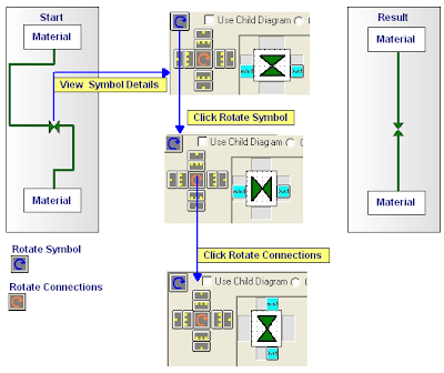
Rotating Symbols
The latest version of ControlDraw has added the ability to rotate symbols and their connection points easily. The illustration below shows how to change a horizontal valve to a vertical one.
This is very useful when re-organising diagrams to improve the process flow, for example when designing an HMI after starting with a P&ID type layout.
This is very useful when re-organising diagrams to improve the process flow, for example when designing an HMI after starting with a P&ID type layout.

Wednesday, 10 February 2010
Requirements Analysis Progress Biotech plant
A video showing some more modelling is here
http://www.controldraw.co.uk/Movies/BiotechPlant2.html
This shows the development of the model to include BioReactor diagrams, (but not the details, that will follow)
It shows how to create a polymorphic diagram and it instances
http://www.controldraw.co.uk/Movies/BiotechPlant2.html
This shows the development of the model to include BioReactor diagrams, (but not the details, that will follow)
It shows how to create a polymorphic diagram and it instances
Sunday, 7 February 2010
Requirements Analysis Progress report
There are so far about 20 people who have expressed interest in following and contributing to this, and many more listening, judging from the number of visitors here.
One person has offered a process, in fact a complete plant!
" The process starts in the cell culture lab where biologicaly engineered cells are taken from a cell bank and grown in lab scale fermentation process until enough cells are produced to seed the first industrial fermentor. Process flow is : cell Culture - Fermentation- Harvest- Recovery- Purification - Freezing. Upstream Area, Midstream Area, and Downstream Area are the main first level of physical models in the two trains. "
Unfortunately there are no P&ID's or process descriptions available, so it is not good basis to proceed with. But some modelling is possible - see
Monday, 1 February 2010
A free peer reviewed automation design model for your process!
ControlDraw Ltd proposes to carry out and show online the development of functional requirement of a readers process.
Readers will define the process that will be used.
Readers will contribute by helping to choose which reader’s process we start with, and by reviewing the documents as they develop. This will be done using LinkedIn Groups
The Process
This could be a portion of a process plant, say a couple of process units.It may be batch or continuous
Ideally this will be one that is real and is soon to be automated. Even if you have already started – you might like to use the exercise to compare your own design.
Source information
Please send ,in the first place, a brief (but not too brief) description of your process. You must also be able to supply P&ID’s no more than 3. As this process will be carried out publicly you must accept that anything you send will be published online.
This will of course use ControlDraw, but others (especially those that promote their own methodologies) are invited to do the same using their normal documentation system.
Here is an overview of the plan

Subscribe to:
Posts (Atom)

