Ever since P&ID’s were first drawn, tag names have been used to identify the instruments. And as they are intended to identify every single instrument, the tags have to be unique.
More than that, the tags always have some meaning, providing a clue as to the purpose and location of the instrument.
Tag naming is one of the first things you need to understand when you start a new project, because most projects have different ways of tagging.
How are Tags constructed?
Generally they have a letter prefix, a number or code, and often a suffix.
Conventionally these tagnames were allocated by instrument engineers whilst at the same time keeping a record of the used tag names in an Instrument Index. More modern CAD systems may keep the index and tags at the same time.
The ISA S5.1 ISA S5.1 standard, codes for Process Instrumentation provides a basis for the letter parts, but not for the number part, and methods of assigning these vary from company to company and even from plant to plant. You can always work out that PIC (or maybe PC) means a pressure indicating controller. But the next part, 1299 say or r123- or whatever is not obvious. Whenever I start working with P&ID I ask for the Equipment/Tagging standard, no two are the same! The standards cover much more than just instruments, for example equipment tags (R for reactor etc), the Area numbers and much more has a company standard. I get bored by the pipe naming.
One classic scheme is to number the instruments within the P&ID, and with part of the P&ID number in the tag. Often In turn the P&ID drawing number contains a higher level, say an area.
So we might have TIC3012-5 where 30 is the area, 12 indicates the twelfth PID in that area and 5 is the fifth Temperature measurement on the P&ID.
A more advanced scheme used by many practitioners is to base Tags on the Equipment number, so the Tags relate to the equipment, and even better so that if there are several similar equipment items the tags within each are the same.
For example, V3249-01 (or perhaps R3249-V01) might be the first valve in reactor R3249, V3250-01 the first valve in reactor R3250, and so on.
Some also have a standard so that similar items have similar sub-number, even in different type of equipment, for example Discharge valves are always V####-01
But when it comes to describing – or even programming – a controlled entity such as a
Unit or Equipment module, it is very useful to have some things that the classic method does not cover. One is Tagnames that are consistent within objects so when you look inside two similar objects (say 2 reactors) the Tags are the same – at least when you exclude the part that identifies which reactor. Then you only have to use nice short names. like V01 or FC02. It can save a lot of time.
Another issue is that, on an HMI, long tag names are unfriendly and clutter the screen. Yes, the best graphics have an option to not display the tagnames, but when you do show them short ones are easier on the eye. And combining Equipment based tagging with Unit relative graphics makes it possible.
The ISA letter parts have a problem - they are based on a very old concept – panel instruments.
In particular the use of the A for alarm letter has become almost a distraction. The A letter meant something in the old days, it might imply a need to use a trip amp and an annunciator lamp, things that had to be purchased. Now, everything can have an alarm, do you really want to change the P&ID because you added an alarm?
Similarly using I to show that something should be displayed? I would hope that everything should be displayable.
The reality is often that there are inconsistencies in the P&ID tag names, even when the tagging scheme is equipment based. (For example when the P&ID tagging has a shared common resource ‘inside’ the first equipment that uses it)
What’s all this got to do with ControlDraw?
ControlDraw provides several ways to handle this:
The External Tag can be set to match whatever the P&ID tag is.
Variants can often be used to reconcile inconsistent tags
Clones can be used to position an object within the P&ID Equipment but still in the right module
Scripts can extract the information from the tag and use it consistently.
Extract the meaning of the Tags with Scripts
Now, whatever the tag naming scheme, there is always some useful information contained within the tag name. And ControlDraw provides several useful ways to deploy that information. The most powerful is by using Scripts.
The Scripts can use parts of the hierarchy of tagnames, for example to set the Engineering Units according to the instrument letters.
TagPrefix0 is the first letters of the lowest level in the hierarchy of tagnames
Select Case TagPrefix0
Case "FT","FI","FIA"
CalcTag = "m3/hr"
Case "PT","PI","PIA"
CalcTag = "Bar"
Case "TT","TI","TIA"
CalcTag = "DegC"
Case "LT","LI","LIA", "CV", "FCV", "LCV","PCV", "TCV"
CalcTag = "%"
Case Else
End Select
Friday, 9 October 2009
Monday, 21 September 2009
Process Flow Sheets with ControlDraw
Did you know that ControlDraw can produce Process Flow Sheets that show process flows and the material properties for equipment and lines. This is achieved by using Symbol Data - name value pairs that you can set for each symbol, or by a matrix.
An example and explanation is provided in the latest Sample Models.
And of coure, like pretty well everything in ControlDraw (and unlike say Visio) the data becomes available for use in Queries and even calculations.
 This is achieved by using Symbol Data - name value pairs that you can set for each symbol, or by a matrix.
An example and explanation is provided in the latest Sample Models.
And of coure, like pretty well everything in ControlDraw (and unlike say Visio) the data becomes available for use in Queries and even calculations.
Tips on Drawing Diagrams
Swap two objects:
You can very quickly swap two objects by dragging one onto anotherr.
An example might be where you want to move a step in an SFC.
Normally the Swap option is only offered when the two objects have the same class but if you hold down Shift then it apples to objects of any class
You can very quickly swap two objects by dragging one onto anotherr.
An example might be where you want to move a step in an SFC.
Normally the Swap option is only offered when the two objects have the same class but if you hold down Shift then it apples to objects of any class
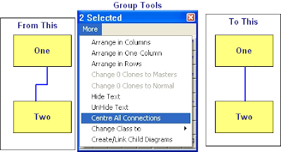
Centre Connections:
If you want to centre the connections between symbols it is very easy using the Centre all connections option in the Group More menu, this will place all the connection points at the mid point of the side they are on.
If you want to centre the connections between symbols it is very easy using the Centre all connections option in the Group More menu, this will place all the connection points at the mid point of the side they are on.
Change Case
It is really annoying to find that the text you have just typed is all in UPPER CASE!
Well, just like MS Word, with ControlDraw it is easy to fix, just use Shift-F3 and the text (for example a Tagname or Object description) will toggle between Upper, Lower and the First Letter Upper and the rest lower.
Well, just like MS Word, with ControlDraw it is easy to fix, just use Shift-F3 and the text (for example a Tagname or Object description) will toggle between Upper, Lower and the First Letter Upper and the rest lower.
Editing Line Positions
 Double click a line and if it has more that two segments each segment that is not at an end of the line shows a number in the middle. You can drag this to move the connection segment.
Monday, 10 August 2009
Showing Instance Data on diagrams
In the in the Reviewer you can select Print All instances of Current Diagram, with Real or External Tags.
When printing the diagram instance any "ClassFieldObject" type Special symbols on a diagram displays the values for the diagram instance.
This is useful for creating for example Instrument Specification type diagrams.
Similarly if a UserQuery contains {CurrentInstance} then the data is display for the selected instance.
Thursday, 16 July 2009
Using ControlDraw to create an Instrument Index and IO List
It is quick and easy to produce an Instrument Index and IO List using ControlDraw
One simple way is to create a top level diagram that shows the process layout (for example Rooms or Plant areas) and then to place Instrument objects on the diagrams for each area/room.
In order to get the IO List, each instrument type should then be shown on a diagram containing the IO Objects. Each Instrument should be linked as a parent to the relevant Instrument Type Diagram.
It is with the more recent versions of ControlDraw very quick to create the diagrams for each area/room
So if the first diagram is a Layout like this (each has the class Unit)

You can select all and then in the Group Tool use >More >Create/Link Child Diagrams

Result

Then place instruments in each room. Make them parents of Instrument Type diagrams that contain the relevant IO
A demonstration model showing this will be published shortly
Thursday, 9 July 2009
10 Years in Business - New licensing model lower cost
ControlDraw has now been over 10 Years in Business. And for a short time licenses are available at lower costs. Furthermore and as previously mentioned there is now a New licensing model.
This includes licenses for use on smaller projects so that smaller companies can get all the benefits of using ControlDraw at a much lower cost than before.
For example, Starter Licenses provide all the modelling that a full license provides but with limits on the overal size of the model. These are still enough for a small process cell with a couple of units defined in great detail.
There are also very cheap licenses for students and personal users.
Online purchasing is also now available.
Friday, 22 May 2009
New licensing model lower cost
ControlDraw will soon be announcing a new pricing scheme for our users
This will include very low cost licenses for personal users and students, and lower prices for small companies such as systems integrators.
ControlDraw has now completed 10 Years in business
Monday, 18 May 2009
Programming Equipment States Efficiently
State based control is a method of defining the required states of some equipment and then driving the equipment to one of these states, typically where a Phase step sets the Equipment States. ControlDraw has long supported this method as it provides a very efficient method of representing functional requirements. An Equipment State Matrix can show the required states of all the modules in the Equipment entity, for example:


So, to help PLC/DCS programmers with this, the latest version of ControlDraw has added a function to generate the data table in a form that is compact and can be easily entered into a PLC or similar. It compacts all the values in the rows into as small a memory block as possible.
(Note - if PCS's had a language that supported such multi-dimensional arrays this would not be needed, however that is not something that I have in practise seen.)
View > Matrix Data Table >Matrix as Boolean for example generates the following text that you can copy to the clipboard:
Row Bool Name
0 00100 'Shutdown
1 00001 'Ready
2 01100 'Fast Fill
3 10100 'Slow Fill
4 00000 'Mix
5 00110 'Transfer
---- Mapping:
Bits required = 5
Bits 0 to 1 set EM02
Bit 2 sets em Fixed Speed Agitator
Bits 3 to 4 set em Feed
You can also generate the table as integers, hex or octal
Note - this is now part of the standard S88 Reference model library that comes with ControlDraw
Tuesday, 28 April 2009
Building the database
This shows how to build the object and instance tables from a model.
Note - it is only the first time you do this or after you change the data design that you have to build the tables in the Data Designer.
Note also how inherited fields may require that you run Update Derived fields more than once, as the values cascade down the levels of the hierarchy
Wednesday, 25 March 2009
Project manage your models
As ControlDraw has been used over the years by people working on large projects, there has of course been a spotlight on the progress of the development of the models. As a result of this there are now many facilities in CD to track and manage progress. For example the ability to set the Review status of diagrams, and to lock them when key milestones are achieved, the backup archive, the Reviewer and the compare functions. So, here quickly are the main functions that you should use for project managing your models.
First, backups and issues
Backing up is more than just a matter of not losing your models, it is a way of taking a snapshot of a model that can be used for comparison later.

Handling Review Meetings
Before - Backup (or better raise the Issue) and save the backup in an archive (ControlDraw makes this very easy)- then review the archive, do not develop the model in a review meeting. If you want to develop the model in a meeting call it a development meeting. And backup before.
After - use reviewer to compare before and after
First, backups and issues
Backing up is more than just a matter of not losing your models, it is a way of taking a snapshot of a model that can be used for comparison later.
Handling Review Meetings
Before - Backup (or better raise the Issue) and save the backup in an archive (ControlDraw makes this very easy)- then review the archive, do not develop the model in a review meeting. If you want to develop the model in a meeting call it a development meeting. And backup before.
After - use reviewer to compare before and after
Next , Diagram Review Status
Each diagram in a model has a review status, which you set from the diagram details or the list of diagrams in >Database >Views
You can use these to establish the progress on each diagram.
It is also good practise to lock diagram once they have been approved, issued for implementation and so on. As well as preventing accidental change to a diagram, locking them enables the finest level of version control whereby you can unlock a diagram, edit it, and then record the changes along with the reason for them.
Automatically Filling Instance Fields
It is possible to set up rules that ControlDraw uses to automatically populate instance data.
This can be done in two primary ways, Symbol Data values and Special Defaults
Special Defaults are entries that are made into the Default value when defining the fields in the Data Designer
Options are:
!Left PTag # Use the left #letters of the Symbol Tagname
!Left UserText # Use the left #letters of the Symbol User Text
!Caption Use the Symbol Caption
!AltCaption Use the Symbol AltCaption
!Inherit Obtain the value from the same named field in the parent instance
!Script Calculate a tag using a tagging script. This can use complex rules to work out a string value to enter
Symbol Data values are values set in in the Symbol Details - these set the value in the same named field in the symbol instances, overriding an other settings such as the Default value
This shows how it all works, click to enlarge

Monday, 23 March 2009
Recipe to Equipment Linking

An EPE (Equipment Procedural Element) is a an object whose class has the Type set as Procedural that is contained on a diagram where the diagram class Has the Type set as Normal.
If the EPE is also shown on a diagram whose class has the Type set as Procedural eg Recipe Procedure, Unit Procedure, Operation or Phase then it is deduced that it is a Referred or Shared EPE
An RPE (Recipe Procedural Element) is a an object whose class has the Type set as Procedural that is contained on a diagram where the diagram class Has the Type set as Procedural
If the EPE is directly referred to by using a SymbolClone or a SymbolCopy special object in the Recipe Procedure and it's Descendants then it is shown as (Referred)
If the EPE is not directly referred to but is the parent of an EPE that is also the child of an EPE on an equipment diagram then is is shown as (# Sharing) where # is the number of equipment diagrams that have the EPE.
State Based Control
There is a new White Paper on ControlGlobal.com called "The Benefits of State Based Control" written by David A. Huffman from ABB
Walt Boyes calls it a "very important white paper". It is quite good and I recommend readers, specially those working in the Continuous process industries, to download it. You have to register with ControlGlobal to get it, but that is worth doing anyway.
The paper does not claim that SBC is new, and indeed it is not. In fact SBC - or something very similar, has been the basis for a lot of ControlDraw models since CD was first introduced, in the mid 90's, and that itself was based on previous paper based ways of specifying State Based Control.
And in turn these models were often then implemented using SBC, and on a variety of systems.
The paper also suggest that implementing SBC is something that ABB with it's 800ax system has removed barriers to. That may be so, but the paper is short on details. Interestingly one of the systems that CD models have been used to spcify (and frequently) is Sattline, now owned by ABB themselves. A little known fact is that 800ax is a direct descendant of Sattline, a system that can probably claim to have been the first object oriented DCS, it has been around since the 90's.
Friday, 6 March 2009
Equipment v Recipe in ControlDraw
When I first had ControlDraw working properly, soon after the introduction of Version 2 and the object structure that exists to this day I dithered about whether there should be a separate Class for Equipment phases (etc) Object and Recipe Phases. I decided not to, as I found that the only difference was in their owners (in ControlDraw that is the Parent object that links to the Phase diagram,).
So, if you have a phase in a Recipe procedure that is not also in an equipment item then it must be a procedural phase, if it does exist in the equipment then it is an equipment phase. If in both then it is still an equipment phase, but is referenced by the corresponding Recipe Procedure phase.
Subscribe to:
Posts (Atom)

