Thursday, 15 April 2010

The Transfer Route Queries

You may not know about this although it has been possible for a long time
If you draw a diagram that shows connections between units via common resources there are standard queries that can show a table of the routes, including those that go from unit to unit (single level) , those that go from onne unit to via another unit to the last unit (2 levels) and those that go from a unit to another via two units (3 levels).
The diagram below show a simple example.
For convenience the single level and two level queries are also shown on this diagram using FAV: UserQuery special objects.

Wednesday, 14 April 2010

New - Tag Balloons

The latest version of ControlDraw provides a new way of attaching text to symbols, these are call Tag Balloons and are based on the ISA tag symbols for P&ID's. The picture below shows how to set them and the styles. Click to enlarge. You can now set the tagname to appear separately from the object in a variety of shapes as shown above. You can then drag the tagname to position it relative to the object.

Tag balloons are auto sized and split the first letters before the number part and the remainder.

The position of the tag balloon is stored relative to the object so you can use Copy and Paste Object properties to set other tag balloons the same - just click the Appearance button in Paste Object properties.

Monday, 22 March 2010

Rotating Symbols

The latest version of ControlDraw has added the ability to rotate symbols and their connection points easily. The illustration below shows how to change a horizontal valve to a vertical one.
This is very useful when re-organising diagrams to improve the process flow, for example when designing an HMI after starting with a P&ID type layout.


Wednesday, 10 February 2010

Requirements Analysis Progress Biotech plant

A video showing some more modelling is here
http://www.controldraw.co.uk/Movies/BiotechPlant2.html
This shows the development of the model to include BioReactor diagrams, (but not the details, that will follow)
It shows how to create a polymorphic diagram and it instances

Sunday, 7 February 2010

Requirements Analysis Progress report

There are so far about 20 people who have expressed interest in following and contributing to this, and many more listening, judging from the number of visitors here.

One person has offered a process, in fact a complete plant!

" The process starts in the cell culture lab where biologicaly engineered cells are taken from a cell bank and grown in lab scale fermentation process until enough cells are produced to seed the first industrial fermentor. Process flow is : cell Culture - Fermentation- Harvest- Recovery- Purification - Freezing. Upstream Area, Midstream Area, and Downstream Area are the main first level of physical models in the two trains. "

Unfortunately there are no P&ID's or process descriptions available, so it is not good basis to proceed with. But some modelling is possible - see

Monday, 1 February 2010

A free peer reviewed automation design model for your process!

ControlDraw Ltd proposes to carry out and show online the development of functional requirement of a readers process.

Readers will define the process that will be used.

Readers will contribute by helping to choose which reader’s process we start with, and by reviewing the documents as they develop. This will be done using LinkedIn Groups

The Process
This could be a portion of a process plant, say a couple of process units.It may be batch or continuous
Ideally this will be one that is real and is soon to be automated. Even if you have already started – you might like to use the exercise to compare your own design.


Source information
Please send ,in the first place, a brief (but not too brief) description of your process. You must also be able to supply P&ID’s no more than 3. As this process will be carried out publicly you must accept that anything you send will be published online.

This will of course use ControlDraw, but others (especially those that promote their own methodologies) are invited to do the same using their normal documentation system.

Here is an overview of the plan


Friday, 9 October 2009

Tag Naming - P&ID and in ControlDraw

Ever since P&ID’s were first drawn, tag names have been used to identify the instruments. And as they are intended to identify every single instrument, the tags have to be unique.
More than that, the tags always have some meaning, providing a clue as to the purpose and location of the instrument.
Tag naming is one of the first things you need to understand when you start a new project, because most projects have different ways of tagging.

How are Tags constructed?
Generally they have a letter prefix, a number or code, and often a suffix.
Conventionally these tagnames were allocated by instrument engineers whilst at the same time keeping a record of the used tag names in an Instrument Index. More modern CAD systems may keep the index and tags at the same time.
The ISA S5.1 ISA S5.1 standard, codes for Process Instrumentation provides a basis for the letter parts, but not for the number part, and methods of assigning these vary from company to company and even from plant to plant. You can always work out that PIC (or maybe PC) means a pressure indicating controller. But the next part, 1299 say or r123- or whatever is not obvious. Whenever I start working with P&ID I ask for the Equipment/Tagging standard, no two are the same! The standards cover much more than just instruments, for example equipment tags (R for reactor etc), the Area numbers and much more has a company standard. I get bored by the pipe naming.
One classic scheme is to number the instruments within the P&ID, and with part of the P&ID number in the tag. Often In turn the P&ID drawing number contains a higher level, say an area.
So we might have TIC3012-5 where 30 is the area, 12 indicates the twelfth PID in that area and 5 is the fifth Temperature measurement on the P&ID.
A more advanced scheme used by many practitioners is to base Tags on the Equipment number, so the Tags relate to the equipment, and even better so that if there are several similar equipment items the tags within each are the same.
For example, V3249-01 (or perhaps R3249-V01) might be the first valve in reactor R3249, V3250-01 the first valve in reactor R3250, and so on.
Some also have a standard so that similar items have similar sub-number, even in different type of equipment, for example Discharge valves are always V####-01

But when it comes to describing – or even programming – a controlled entity such as a
Unit or Equipment module, it is very useful to have some things that the classic method does not cover. One is Tagnames that are consistent within objects so when you look inside two similar objects (say 2 reactors) the Tags are the same – at least when you exclude the part that identifies which reactor. Then you only have to use nice short names. like V01 or FC02. It can save a lot of time.
Another issue is that, on an HMI, long tag names are unfriendly and clutter the screen. Yes, the best graphics have an option to not display the tagnames, but when you do show them short ones are easier on the eye. And combining Equipment based tagging with Unit relative graphics makes it possible.

The ISA letter parts have a problem - they are based on a very old concept – panel instruments.
In particular the use of the A for alarm letter has become almost a distraction. The A letter meant something in the old days, it might imply a need to use a trip amp and an annunciator lamp, things that had to be purchased. Now, everything can have an alarm, do you really want to change the P&ID because you added an alarm?
Similarly using I to show that something should be displayed? I would hope that everything should be displayable.


The reality is often that there are inconsistencies in the P&ID tag names, even when the tagging scheme is equipment based. (For example when the P&ID tagging has a shared common resource ‘inside’ the first equipment that uses it)

What’s all this got to do with ControlDraw?

ControlDraw provides several ways to handle this:
The External Tag can be set to match whatever the P&ID tag is.
Variants can often be used to reconcile inconsistent tags
Clones can be used to position an object within the P&ID Equipment but still in the right module
Scripts can extract the information from the tag and use it consistently.

Extract the meaning of the Tags with Scripts
Now, whatever the tag naming scheme, there is always some useful information contained within the tag name. And ControlDraw provides several useful ways to deploy that information. The most powerful is by using Scripts.
The Scripts can use parts of the hierarchy of tagnames, for example to set the Engineering Units according to the instrument letters.
TagPrefix0 is the first letters of the lowest level in the hierarchy of tagnames
Select Case TagPrefix0
Case "FT","FI","FIA"
CalcTag = "m3/hr"
Case "PT","PI","PIA"
CalcTag = "Bar"
Case "TT","TI","TIA"
CalcTag = "DegC"
Case "LT","LI","LIA", "CV", "FCV", "LCV","PCV", "TCV"
CalcTag = "%"
Case Else
End Select

Monday, 21 September 2009

Process Flow Sheets with ControlDraw

Did you know that ControlDraw can produce Process Flow Sheets that show process flows and the material properties for equipment and lines. This is achieved by using Symbol Data - name value pairs that you can set for each symbol, or by a matrix.
An example and explanation is provided in the latest Sample Models.
And of coure, like pretty well everything in ControlDraw (and unlike say Visio) the data becomes available for use in Queries and even calculations.

Tips on Drawing Diagrams

Swap two objects:
You can very quickly swap two objects by dragging one onto anotherr.
An example might be where you want to move a step in an SFC.
Normally the Swap option is only offered when the two objects have the same class but if you hold down Shift then it apples to objects of any class
Centre Connections:
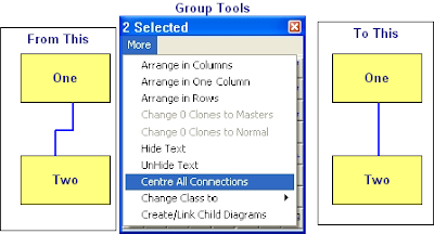
If you want to centre the connections between symbols it is very easy using the Centre all connections option in the Group More menu, this will place all the connection points at the mid point of the side they are on.


Change Case
It is really annoying to find that the text you have just typed is all in UPPER CASE!
Well, just like MS Word, with ControlDraw it is easy to fix, just use Shift-F3 and the text (for example a Tagname or Object description) will toggle between Upper, Lower and the First Letter Upper and the rest lower.

Editing Line Positions

Double click a line and if it has more that two segments each segment that is not at an end of the line shows a number in the middle. You can drag this to move the connection segment.

Monday, 10 August 2009

Showing Instance Data on diagrams

In the in the Reviewer you can select Print All instances of Current Diagram, with Real or External Tags.

When printing the diagram instance any "ClassFieldObject" type Special symbols on a diagram displays the values for the diagram instance.

This is useful for creating for example Instrument Specification type diagrams.

Similarly if a UserQuery contains {CurrentInstance} then the data is display for the selected instance.