Monday, 21 September 2009

Process Flow Sheets with ControlDraw

Did you know that ControlDraw can produce Process Flow Sheets that show process flows and the material properties for equipment and lines. This is achieved by using Symbol Data - name value pairs that you can set for each symbol, or by a matrix.
An example and explanation is provided in the latest Sample Models.
And of coure, like pretty well everything in ControlDraw (and unlike say Visio) the data becomes available for use in Queries and even calculations.

Tips on Drawing Diagrams

Swap two objects:
You can very quickly swap two objects by dragging one onto anotherr.
An example might be where you want to move a step in an SFC.
Normally the Swap option is only offered when the two objects have the same class but if you hold down Shift then it apples to objects of any class
Centre Connections:
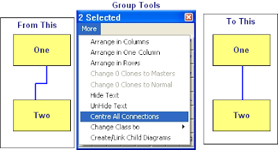
If you want to centre the connections between symbols it is very easy using the Centre all connections option in the Group More menu, this will place all the connection points at the mid point of the side they are on.


Change Case
It is really annoying to find that the text you have just typed is all in UPPER CASE!
Well, just like MS Word, with ControlDraw it is easy to fix, just use Shift-F3 and the text (for example a Tagname or Object description) will toggle between Upper, Lower and the First Letter Upper and the rest lower.

Editing Line Positions

Double click a line and if it has more that two segments each segment that is not at an end of the line shows a number in the middle. You can drag this to move the connection segment.

Monday, 10 August 2009

Showing Instance Data on diagrams

In the in the Reviewer you can select Print All instances of Current Diagram, with Real or External Tags.

When printing the diagram instance any "ClassFieldObject" type Special symbols on a diagram displays the values for the diagram instance.

This is useful for creating for example Instrument Specification type diagrams.

Similarly if a UserQuery contains {CurrentInstance} then the data is display for the selected instance.

Thursday, 16 July 2009

Using ControlDraw to create an Instrument Index and IO List

It is quick and easy to produce an Instrument Index and IO List using ControlDraw
One simple way is to create a top level diagram that shows the process layout (for example Rooms or Plant areas) and then to place Instrument objects on the diagrams for each area/room.
In order to get the IO List, each instrument type should then be shown on a diagram containing the IO Objects. Each Instrument should be linked as a parent to the relevant Instrument Type Diagram.
It is with the more recent versions of ControlDraw very quick to create the diagrams for each area/room
So if the first diagram is a Layout like this (each has the class Unit)


You can select all and then in the Group Tool use >More >Create/Link Child Diagrams


Result


Then place instruments in each room. Make them parents of Instrument Type diagrams that contain the relevant IO
A demonstration model showing this will be published shortly

Thursday, 9 July 2009

10 Years in Business - New licensing model lower cost

ControlDraw has now been over 10 Years in Business. And for a short time licenses are available at lower costs. Furthermore and as previously mentioned there is now a New licensing model.
This includes licenses for use on smaller projects so that smaller companies can get all the benefits of using ControlDraw at a much lower cost than before.

For example, Starter Licenses provide all the modelling that a full license provides but with limits on the overal size of the model. These are still enough for a small process cell with a couple of units defined in great detail.

There are also very cheap licenses for students and personal users.

Online purchasing is also now available.

Friday, 22 May 2009

New licensing model lower cost

ControlDraw will soon be announcing a new pricing scheme for our users
This will include very low cost licenses for personal users and students, and lower prices for small companies such as systems integrators.
ControlDraw has now completed 10 Years in business

Monday, 18 May 2009

Programming Equipment States Efficiently

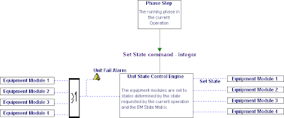
State based control is a method of defining the required states of some equipment and then driving the equipment to one of these states, typically where a Phase step sets the Equipment States. ControlDraw has long supported this method as it provides a very efficient method of representing functional requirements. An Equipment State Matrix can show the required states of all the modules in the Equipment entity, for example:

When it comes to programming this in a Process Control System it is possible to make highly efficient and fast code by deploying the State Matrix as a data table, with the phase steps simply setting a index into the matrix. This really is far more efficient than having each step in a sequence contain all the required device settings and it becomes more efficient the more states and steps there are. The software diagram below shows how this might be done.


So, to help PLC/DCS programmers with this, the latest version of ControlDraw has added a function to generate the data table in a form that is compact and can be easily entered into a PLC or similar. It compacts all the values in the rows into as small a memory block as possible.
(Note - if PCS's had a language that supported such multi-dimensional arrays this would not be needed, however that is not something that I have in practise seen.)

View > Matrix Data Table >Matrix as Boolean for example generates the following text that you can copy to the clipboard:
Row Bool Name
0 00100 'Shutdown
1 00001 'Ready
2 01100 'Fast Fill
3 10100 'Slow Fill
4 00000 'Mix
5 00110 'Transfer
---- Mapping:
Bits required = 5
Bits 0 to 1 set EM02
Bit 2 sets em Fixed Speed Agitator
Bits 3 to 4 set em Feed

You can also generate the table as integers, hex or octal

Note - this is now part of the standard S88 Reference model library that comes with ControlDraw

Tuesday, 28 April 2009

Building the database

This shows how to build the object and instance tables from a model.

Note - it is only the first time you do this or after you change the data design that you have to build the tables in the Data Designer.

Note also how inherited fields may require that you run Update Derived fields more than once, as the values cascade down the levels of the hierarchy

Wednesday, 25 March 2009

Project manage your models

As ControlDraw has been used over the years by people working on large projects, there has of course been a spotlight on the progress of the development of the models. As a result of this there are now many facilities in CD to track and manage progress. For example the ability to set the Review status of diagrams, and to lock them when key milestones are achieved, the backup archive, the Reviewer and the compare functions. So, here quickly are the main functions that you should use for project managing your models.

First, backups and issues
Backing up is more than just a matter of not losing your models, it is a way of taking a snapshot of a model that can be used for comparison later.


Handling Review Meetings

Before - Backup (or better raise the Issue) and save the backup in an archive (ControlDraw makes this very easy)- then review the archive, do not develop the model in a review meeting. If you want to develop the model in a meeting call it a development meeting. And backup before.


After - use reviewer to compare before and after

Next , Diagram Review Status
Each diagram in a model has a review status, which you set from the diagram details or the list of diagrams in >Database >Views
You can use these to establish the progress on each diagram.
It is also good practise to lock diagram once they have been approved, issued for implementation and so on. As well as preventing accidental change to a diagram, locking them enables the finest level of version control whereby you can unlock a diagram, edit it, and then record the changes along with the reason for them.


Automatically Filling Instance Fields

It is possible to set up rules that ControlDraw uses to automatically populate instance data.
This can be done in two primary ways, Symbol Data values and Special Defaults
Special Defaults are entries that are made into the Default value when defining the fields in the
Data Designer
Options are:
!Left PTag # Use the left #letters of the Symbol Tagname
!Left UserText # Use the left #letters of the Symbol User Text
!Caption Use the Symbol Caption
!AltCaption Use the Symbol AltCaption
!Inherit Obtain the value from the same named field in the parent instance
!Script Calculate a tag using a
tagging script. This can use complex rules to work out a string value to enter
Symbol Data values are values set in in the Symbol Details - these set the value in the same named field in the symbol instances, overriding an other settings such as the Default value
This shows how it all works, click to enlarge